| General |
| Power Requirements |
12 V DC (10.8 V to 13.2 V), DC 42 V to 57 V (Camera Input, PoE+ power supply) |
| Current Consumption |
1.0 A (Connector Input), 0.6 A (PoE+ power supply) |
| Ambient Operating Temperature |
0 °C to 40 °C (32 °F to 104 °F) |
| Allowable Humidity Ranges |
10 % to 90 % (no condensation) |
| Storage Temperature |
-20 °C to 50 °C (-4 °F to 122 °F) |
| Mass |
Approx. 3.2 kg (7.05 lb) |
| Dimensions (W x H x D) |
342 mm x 178 mm x 245 mm (13-15/32 inches x 7 inches x 9-21/32 inches)
(excluding protrusions) |
| Connection Supported Equipment |
IP/RS422
AW-UE150W/K, AW-HR140*1, AW-HE130W/K*1*2, AW-HN130W/K*1*2, AW-UE70W/K*1, AW-UN70W/K*1, AW-HE40 Series*1, AW-HN40HW/HK*1, AW-HE38HW/HK*1, AW-HN38HW/HK*1 |
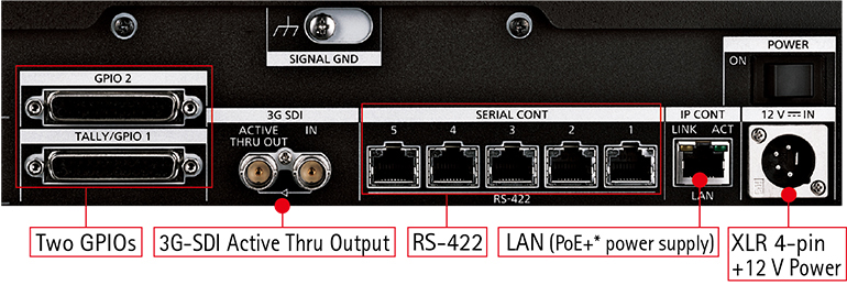
| Input/Output Connectors |
| Input |
DC 12 V IN |
XLR 4‑pin |
| 3G-SDI IN |
SMPTE424M/SMPTE292 / 75 Ω (BNC x 1)
Supported formats:
1080/59.94p*2, 1080/50p*3, 1080/59.94i, 1080/50i, 1080/23.98p, 1080/25p, 1080/23.98PsF, 1080/25PsF |
| Output |
3G-SDI
ACTIVE THRU OUT |
SMPTE292 / 75 Ω (BNC x 1) |
| Input/Output |
IP CONT |
100BASE‑TX
PoE+ input
Connection cable: LAN cable, max. 100 m (328 ft)
• When connecting the unit via a switching hub: Straight cable or a cross cable (category 5 cable), STP (Shielded Twisted Pair) cable recommended
• When connecting the unit directly: Crossover cable (category 5 cable), STP (Shielded Twisted Pair) cable recommended |
| SERIAL CONT (RJ‑45) |
RS‑422 (control signals for remote cameras)
Connecting cable:
Straight cable (category 5e or better shielded cable), max. 1000 m (3280 ft) |
| TALLY OUT |
Open collector output (negative logic)
Maximum voltage resistance DC 24 V, Maximum current 50 mA |
| TALLY/GPIO 1 |
D‑sub 25‑pin, female, inch thread
TALLY IN : 10 inputs (for receiving photocoupler signals)
GPI : 6 inputs (for receiving photocoupler signals)
GPIO : 5 inputs (for receiving photocoupler signals) or 5 outputs (open collector outputs, negative logic)
• Input/output switched with menu settings |
| GPIO 2 |
D‑sub 25‑pin, female, inch thread
GPI : 10 inputs (for receiving photocoupler signals)
GPIO : 10 inputs (for receiving photocoupler signals) or 10 outputs (open collector outputs, negative logic)
• Input/output switched with menu settings
Reserve connectors:
2 connectors (For future expansion feature) |
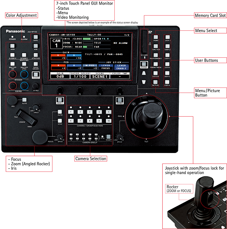
| LCD Display |
7-inch Touch Panel GUI Monitor (WVGA(800×480)) |
| SD Memory Card Slot |
SDHC / SDXC Memory Card Slot x 1 |
| Connection Specifications |
| No. of Connectable Cameras |
200 (IP), 5 (RS422) |
| No. of Camera Selection Buttons |
10 |
| No. of Camera Groups |
20 (10 units per 1 group) |
| Memory |
| Preset Memory |
No. of memory presets 100 |
| Tracing Memory |
No. of cameras |
Cam1 to Cam10 |
| Recording time, no. of memory settings |
Maximum 5 min. total per camera, maximum of 10 settings per camera |
| Other Functions |
| No. of User Assignable Buttons |
6 + up to 10 on the LCD menu |
| Pan / Tilt Speed Adjustment |
7 levels |
| TALLY LED Display Color: |
green / red |